Automatically add devices
ScanBus scans all devices on the EtherCAT network and adds them to KINGSTAR LogicLab automatically. Because ScanBus scans the hardware through KINGSTAR, you must install KINGSTAR and KINGSTAR LogicLab on the same computer to use this feature.
- Make sure all devices you want to use are connected to your computer.
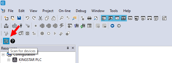
- In the toolbar, click ScanBus.
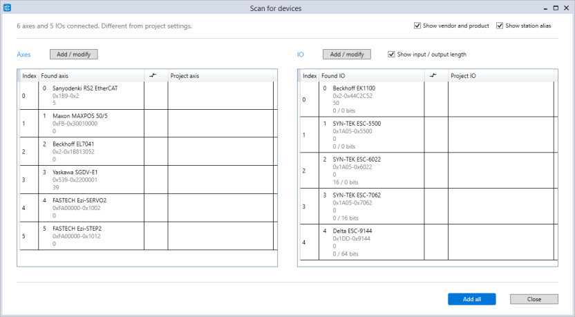
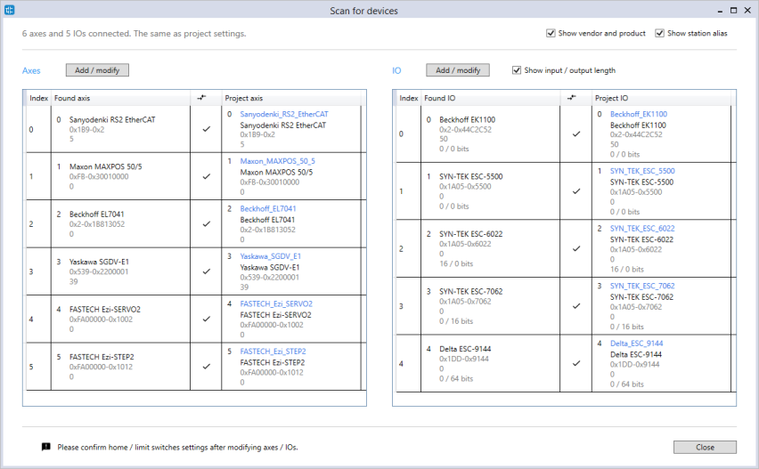
- After the scan is done, the devices will be displayed in the Scan for devices dialog box. Axes are listed on the left and the I/O modules are listed on the right. You have these options:
- If you want to add them all to your project, click Add all.
- If you don't want add any hardware, click Close.
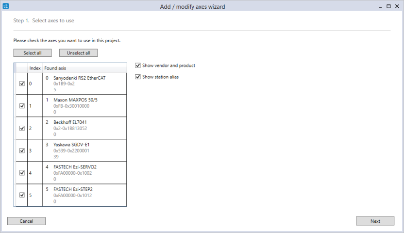
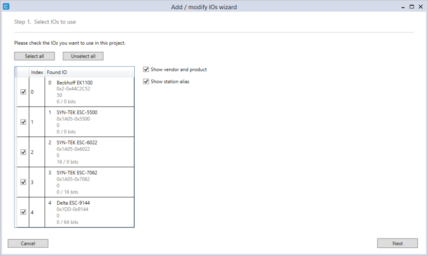
- If you want to select the hardware to add, click Add / modify to display the Add / modify axes wizard or Add / modify IOs wizard.
- Select the axis or I/O you want. You can select the Show vendor and product and Show station alias check boxes to see the vendor ID, product code, and station alias address. When you're done, click Next.
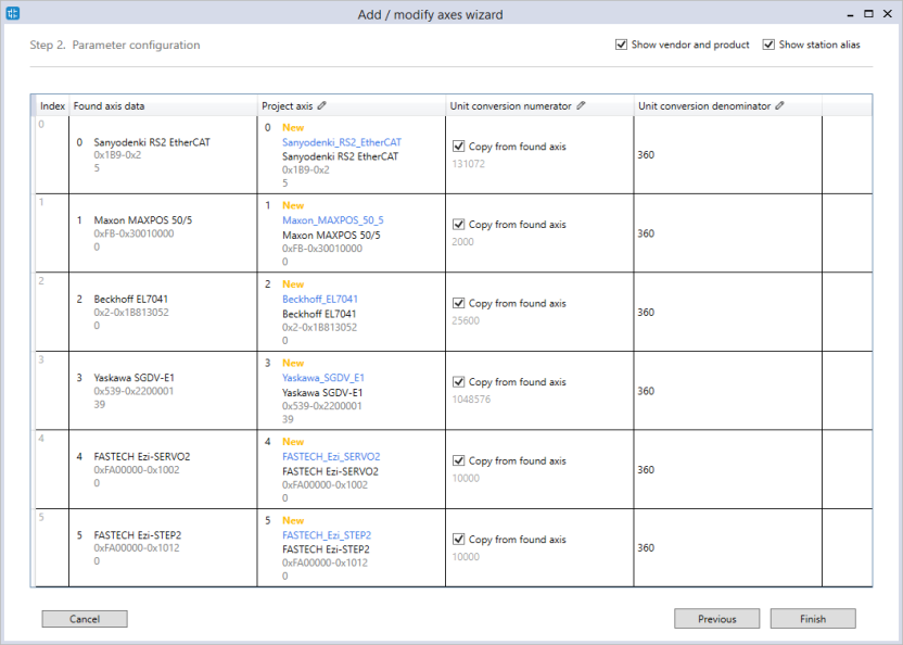
- Edit the hardware information. If the column header shows a pencil icon, it means that column is editable. To edit the information, double-click the cell. When you finish editing, press Enter.
- Found axis data: The axes found on the EtherCAT network.
- Project axis: The axes used in your project. You can change each axis' name.
- Unit conversion numerator: The encoder's resolution that is used as numerator for unit conversion. If the Copy from found axis check box is selected, KINGSTAR will use the encoder's resolution, otherwise it will use the value you entered.
- Unit conversion denominator: The value that is used as the denominator for unit conversion. By default, the unit is converted to degree, so the value is 360. You can change the value if you want to convert to other unit.
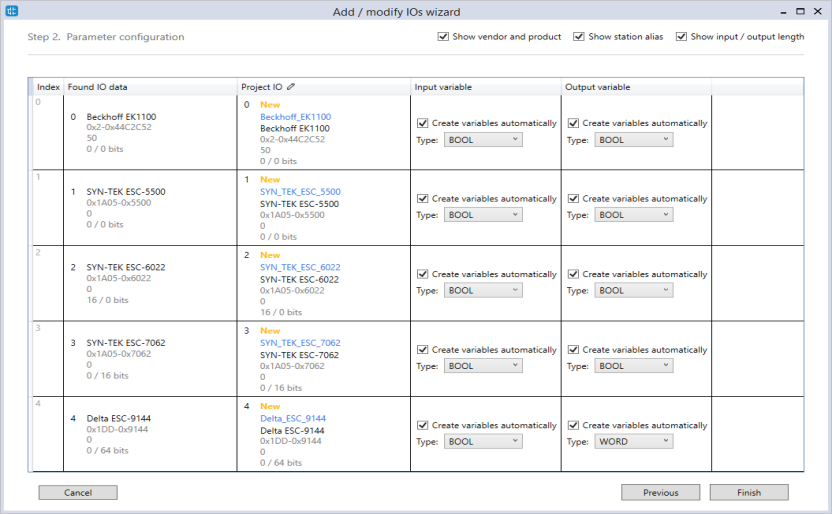
- Found IO data: The I/O modules found on the EtherCAT network.
- Project IO: The I/O modules used in your project. You can change each I/O module's name.
- Input variable: The input variable for the I/O module. If the Create variables automatically check box is selected, LogicLab will create variables automatically using the type you selected, otherwise it won't create any variable. The number of variables is based on the input length.
- Output variable: The output variable for the I/O module.
- In the Scan for devices dialog box, check marks are displayed in the axes and I/Os table. It means the found devices and project devices are mapped successfully. Click OK.
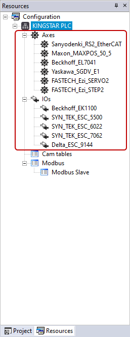
- The devices are added to Resources.
NOTE: If you don't see the ScanBus icon, on the View menu, click Toolbars > KINGSTAR to display it.
NOTE: The station alias is used to identify multiple identical devices with the same Vendor ID and Product code. See AliasAddress in SlaveStatus for more details.
Axes:
I/O modules:
Axes:
For more information about the unit conversion, see SetAxisCountsPerUnit.
I/O modules:
To display each I/O module's input and output length, select the Show input / output length check box in the top-right corner of the page.
When you finish editing, click Finish.
NOTE: When you delete an I/O module, LogicLab will ask if you want to delete its I/O variables. Click Yes to delete them.