Map the real hardware to the added devices
If you add the devices manually and want to apply the real hardware information to them, you can map the real hardware to the device. Mapping is not the necessary step for the manually added devices. You can use your own device settings instead of applying the real hardware information to them, but you need to make sure that your settings can work on the connected hardware properly.
The ways to map axes and I/Os are the same. In this guide, we talk about how to map axes.
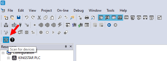
- In the toolbar, click Scanbus.
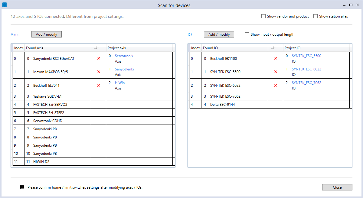
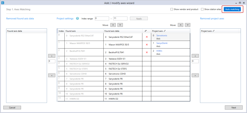
- After the scan is done, the devices will be displayed in the Scan for devices dialog box. Axes are listed on the left and the I/O modules are listed on the right. Found axis are axes found on the EtherCAT network. Project axis and Project IO are the axes and I/O modules you created in the project. In the Axes area, click Add / modify to display the Add / modify axes wizard.
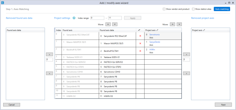
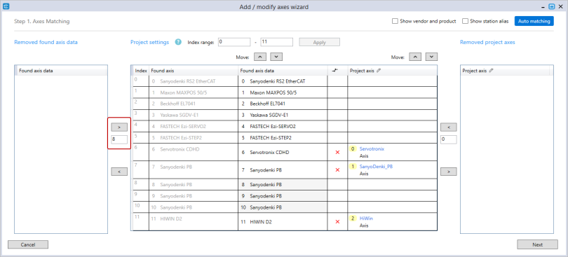
- In Axes Matching, there are a few things you can do:
- Match the axes: match the project axes to the found axes. The hardware information of the found axes will be transferred to the project axes after mapping.
- In the Project axis column, click the axis you want to match. You can hold down CTRL or SHIFT to select multiple axes.
- Click Move Up or Move Down to match the project axis to the found one.
- The indexes of the project axes become yellow after they are moved. After mapping, the indexes of the project axes will be changed to those of the found axes. In this guide, Servotronix, SenyoDenki, and HiWin indexes will be changed to 6, 7, and 11, respectively.
- Automatically match the axes:
- Click Auto matching.
- In the Auto Matching dialog box, select an option to match your axes.
- Match project axes to found axes
- Are the vendor ID and the product code of a project axis the same as those of a found axis? Both vendor ID and product code must match.
- Match found axes to project axes
- Are the vendor ID and the product code of a found axis the same as those of a project axis? Both vendor ID and product code must match.
- Match by their indexes: The project axes are matched to the found axes according to the found axes' indexes.
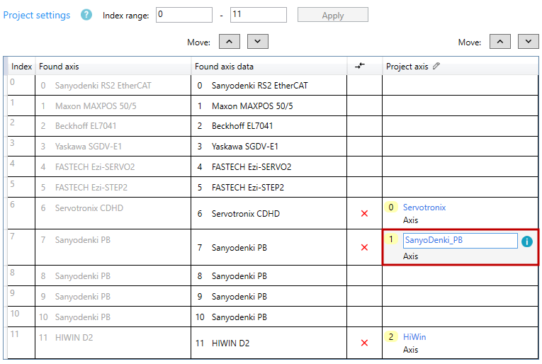
- Rename the axes: in the Project axis column, double-click one of the axes to change its name.
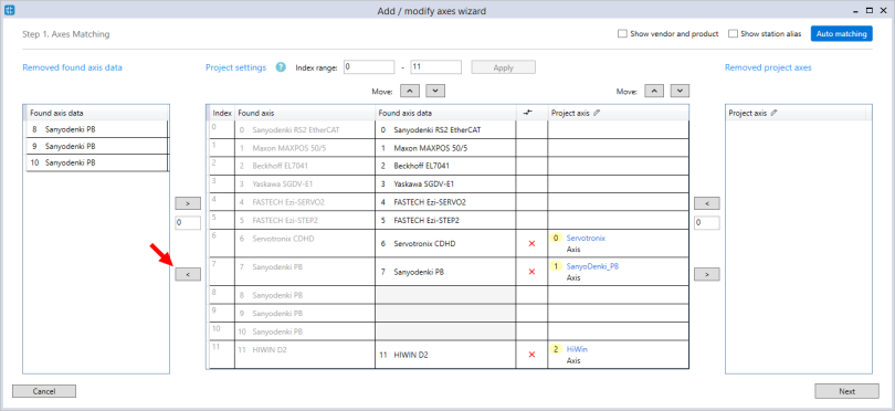
- Remove the axes: remove the unused axes in the project. In this guide, we remove Found axis. Project axis works the same way.
- In the Found axis data column, click the axes you want to remove. You can hold down CTRL or SHIFT to select more than one axis.
- Click < to move the axes to the Removed found axis data list.
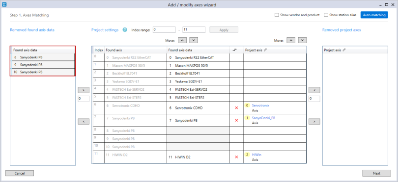
- Add the axes back: add the axes back after you remove them. In this guide, we add Found axis back. Project axis works the same way.
- In the Removed found axis data list, click the axes you want to add. You can hold down CTRL or SHIFT to select more than one axis.
- In the text box below >, enter the starting index for the axes you're adding back. For example, if you enter 1, the index of the first axis added back will be one, the second will be two.
- The axes are added back.
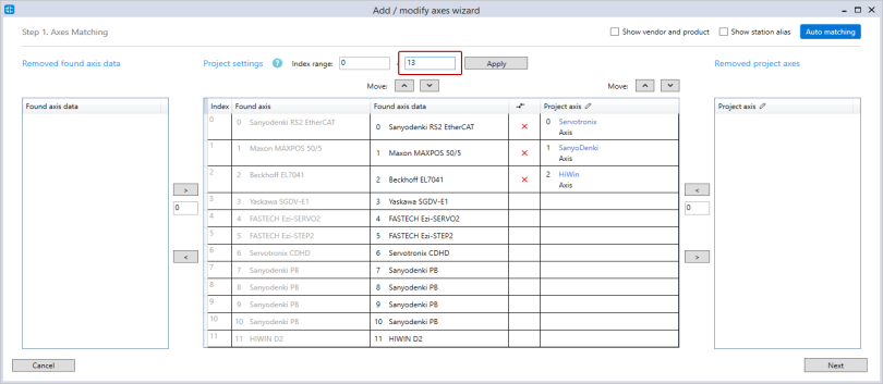
- Change the project index range: you can reduce or expand the index range. If you reduce the range that can't contain all the axes, LogicLab will force some axes to be removed. If you expand the range, but you don't assign any axes to the extra indexes, those indexes will be deleted automatically in Parameter configuration.
- In the Index range box, change the end index. We set it to 13.
- Click Apply. The indexes are added.
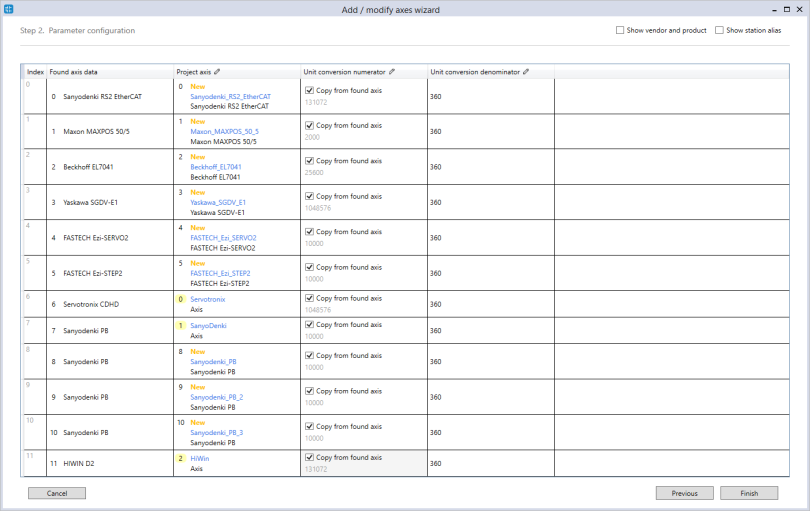
- In Parameter configuration, you can edit axes' names, copy the hardware information, and change the unit the axis uses. Note that in the Unit conversion numerator column, if you select the Copy from found axis check box, the numerator of the found axis will overwrite that of the project axis. For more information about this page, see the step 3 in Automatically add devices.
- In the Scan for devices dialog box, check marks are displayed in the axes and I/Os table. It means the found devices and project devices are mapped successfully. We have matched the axes. Repeat the same process to match the I/O modules.
- The I/O modules are matched. Click Close.
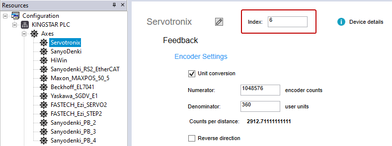
- The devices are mapped and added to Resources. Notice that the index is changed.

LogicLab checks one condition before matching:
If the condition is true, LogicLab will match the project axis to the found axis. If it is false, LogicLab will match the project axis to the found axis according to the found axis' index. The indexes of the project axes may be changed after matching.
LogicLab checks one condition before matching:
If the condition is true, LogicLab will match the found axis to the project axis. If it is false, LogicLab will match the found axis to the project axis according to the project axis' index. The indexes of the found axes may be changed after matching.


NOTE: If you enter an index that has been used by other axis in Found axis, you can't add the axes back. In this guide, we enter 8.

When you finish editing in Axis Matching, click Next.
When you finish editing, click Finish.
NOTE: If a red X mark is displayed, it means the found device and project device can't be mapped because their hardware information is different. To resolve this, in the Add / modify wizard, in Axes Matching or I/Os Matching, move the Project axis or Project I/O to match its counterpart. If the problem persists, check your project axis or I/O settings.