Work with I/O variables
This section describes how to work with I/O variables.
- Add an I/O variable
- Edit an I/O variable
- Reassign an I/O variable
- Unassign an I/O variable
- Delete an I/O variable
- Update the I/O variables
- Change and display the bit address of the I/O variables
Environment:
Our example uses SYNTEK ESC 6022, a 16-bit digital input (DI) module and SYNTEK ESC 7062, a 16-bit digital output (DO) module. Both modules are connected to a SYNTEK ESC 5500 coupler. The outputs of the ESC 7062 module are connected to the inputs of the ESC 6022 module. To create this environment, create a SYNTEK ESC 6022 I/O module using the index 1 and a SYNTEK ESC 7062 I/O module using the index 2 in your project as explained in the Manually add devices section.
When you manually add an I/O module, I/O variables can be add automatically. This section describes how to add the I/O variables manually.
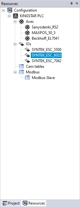
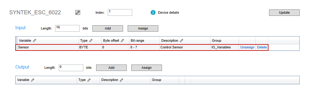
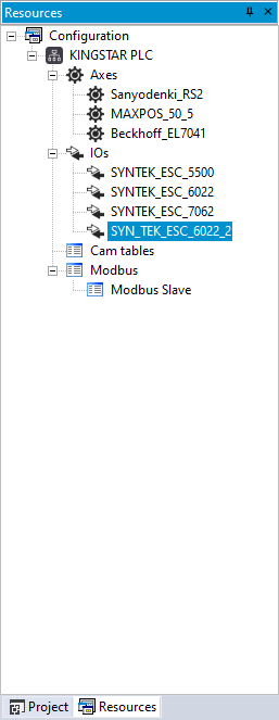
- In the Resources panel to the left, click SYN_TEK_ESC_6022 (one of your I/O module).
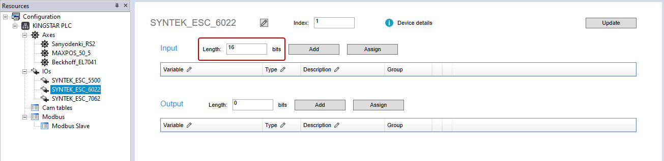
- In the Input area, in the Length box, enter 16. Before adding a variable, you must enter a value for input or output length, so you can add I/O variables. If you want to control a real I/O module, you need to know whether this I/O is an input or output (or have them both) module, and the input and output length of the I/O, so you can enter a correct value for it. In our case, SYNTEK_ESC_6022 is a 16-bit input module. We enter 16 for our I/O's input length.
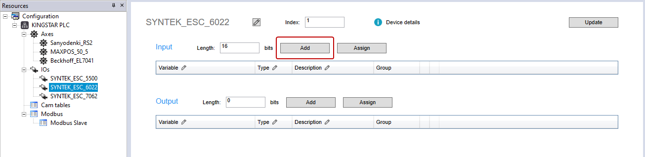
- In the Input area, click Add.
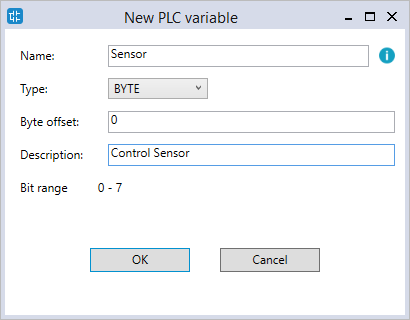
- In the New PLC variable dialog box, enter the following information:
- The variable has been added to the Input table.
-
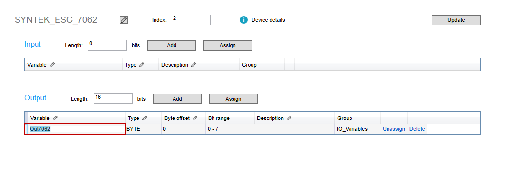
In the Resources panel to the left, click SYN_TEK_ESC_7062. In its Output area, add the variable "Out7062" with the BOOL type. In our case, the output module SYNTEK_ESC_7062 is connected to the input module SYNTEK_ESC_6022. We need to use this module to write a value to 6022, so we create a variable in 7062.
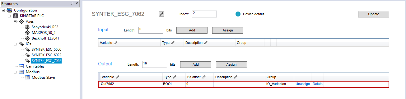
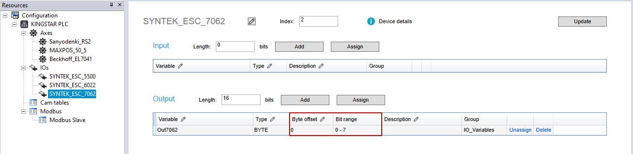
Notice that if a variable is created as BOOL, the Bit offset column will be displayed. If created as BYTE, WORD or other type, the Byte offset and Bit range columns will be displayed.
Name: enter a meaningful name for this variable. We enter "Sensor."
Type: select the variable type. We select BYTE.
Byte offset: offset the variable. We leave it zero.
Description: it's optional to enter the description for this variable to further explain its use. We enter "Control Sensor."
Bit range: displays the bit range according to Type.
When you finish editing, click OK.
After adding an I/O variable, you can edit its attributes directly in the table.
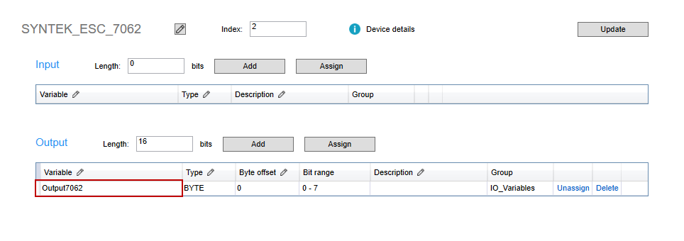
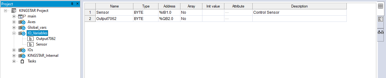
- Notice the pencil icon in the header row. It means that column is editable. For example, we want to change the variable's name to "Output7062," so we double-click the variable name "Out7062" in the Variable cell. The name is highlighted.
- In the Variable cell, modify the variable name and then press Enter. LogicLab will ask if you want to replace all occurrences with the new name. Click Yes.
- The variable's name is changed.

You can reassign an I/O variable from an input (output) of an I/O module to an input (output) of another I/O module. In this guide we move a variable from an input to another input.
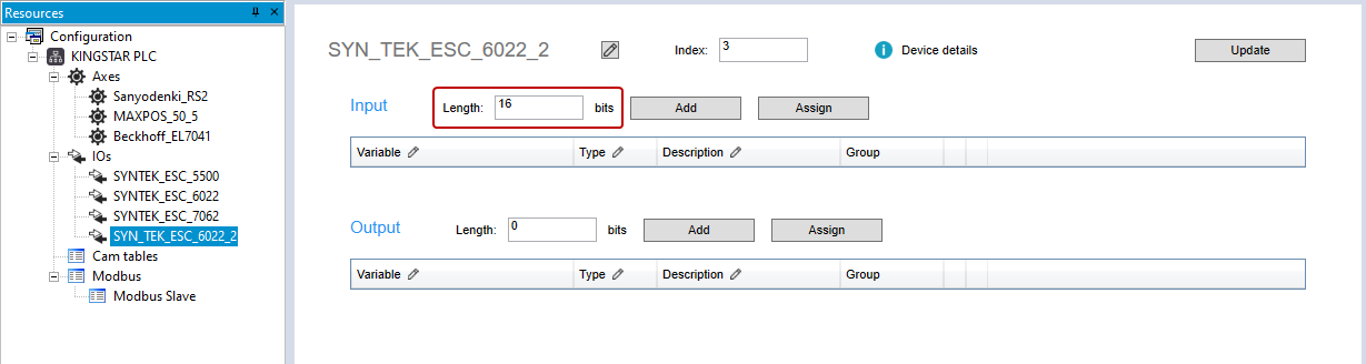
- In the Resources panel to the left, in the IOs list, add an input I/O module. In this guide, we add SYN_TEK_ESC_6022_2.
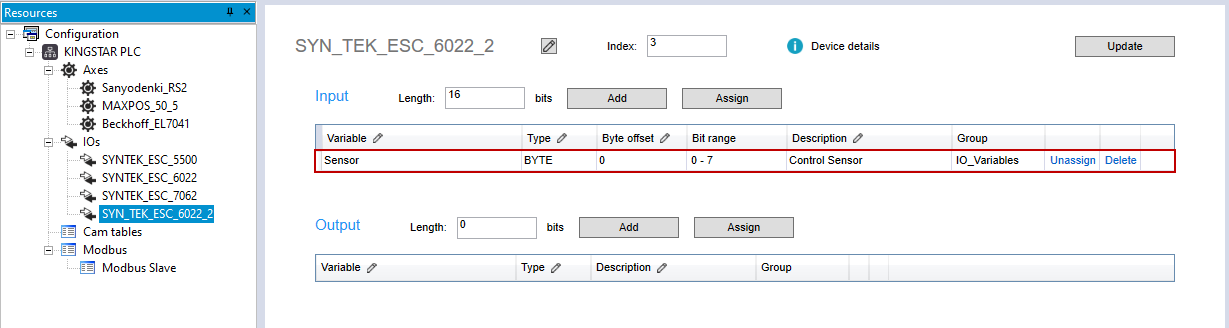
- Click SYN_TEK_ESC_6022_2. In the Input area, in the Length box, enter 16.
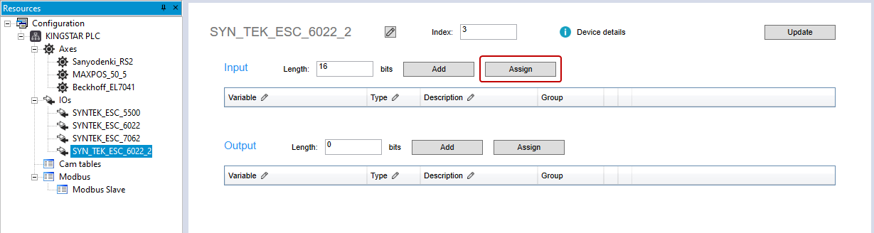
- In the Input area, click Assign.
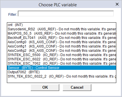
- In the Choose PLC variable dialog box, click a variable you want to reassign and click OK.
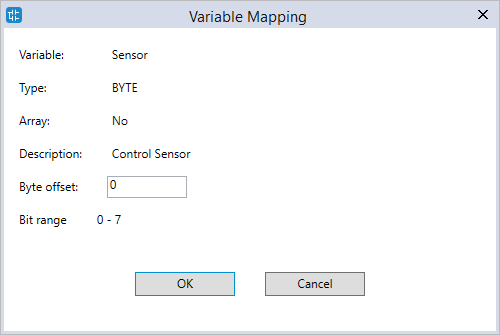
- In the Variable Mapping dialog box, in the Byte offset box, enter an offset value or leave it zero. When you finish editing, click OK.
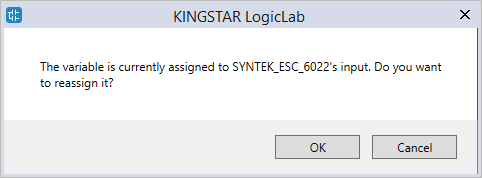
- LogicLab asks if you want to reassign the variable. Click OK.
- The variable is reassigned from the input of SYN_TEK_ESC_6022 to the input of SYN_TEK_ESC_6022_2.
NOTE: When you manually add an I/O module, you can assign the length of the I/O input and output in the Add IO dialog box. If you didn't, you can assign here.
NOTE: When the variable list is long, you can type the variable's name in the Filter box to find your variable.
When you unassign an I/O variable, its address becomes AUTO, which means this variable is not associated with the I/O module and becomes a PLC global variable.
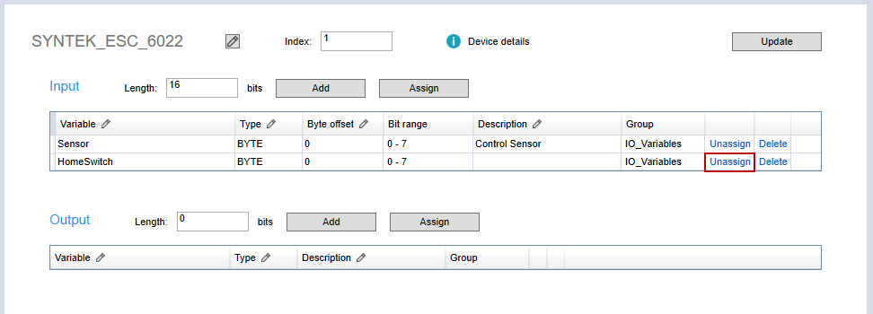
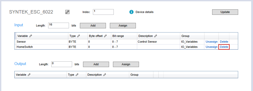
- In the Input area, in the HomeSwitch row (any variable's row), click Unassign.
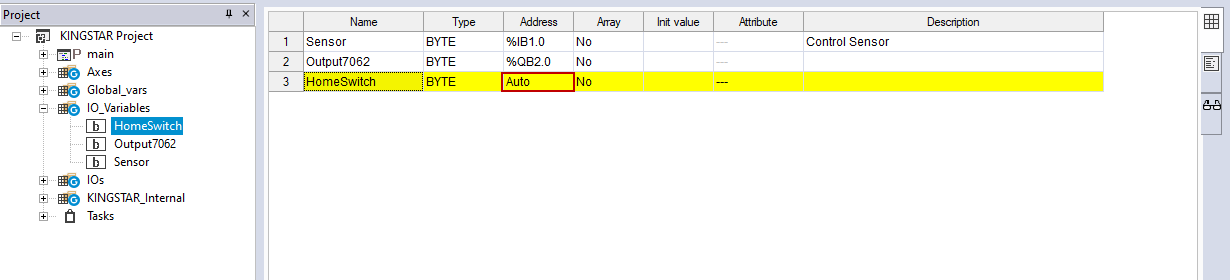
- The unassigned variable disappears, but it is not deleted. In the Project panel, expand the IO_Variables and double-click HomeSwitch. Its address becomes Auto.
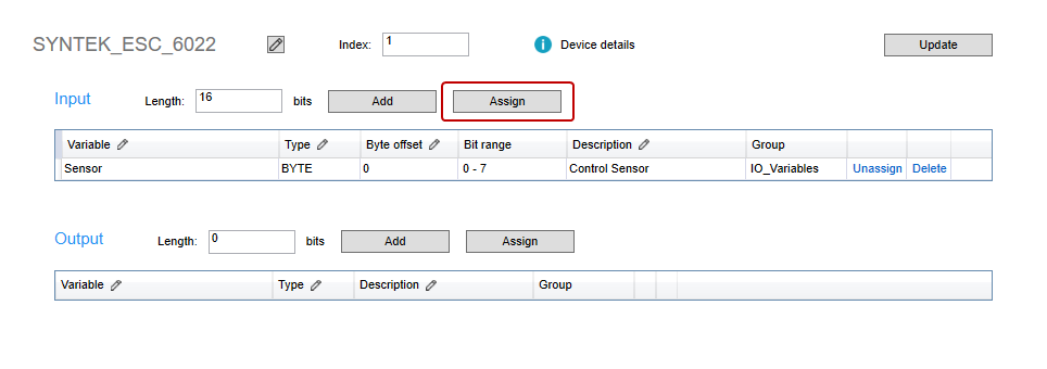
- To reassign HomeSwitch to Input, in the Input area, click Assign.
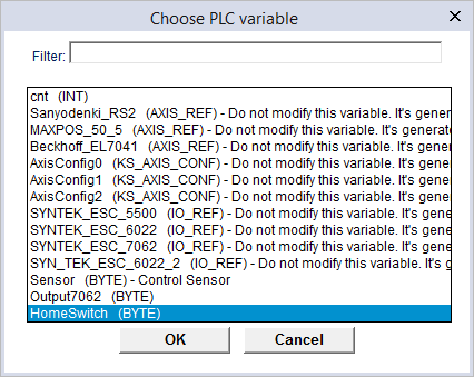
- In the Choose PLC variable dialog box, select HomeSwitch and click OK.
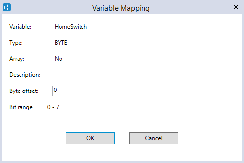
- In the Variable Mapping dialog box, in the Byte offset box, enter an offset value or leave it zero. When you finish editing, click OK.
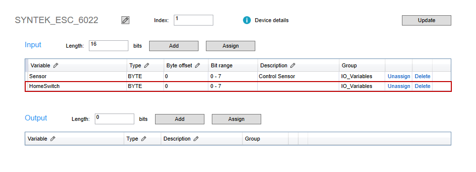
- HomeSwitch is reassigned to Input.
- In the Input area, in the HomeSwitch row, click Delete.
- The variable is deleted. In the Project panel, click I/O_Variables. You can see HomeSwitch is deleted.
NOTE: When you delete an I/O module, LogicLab will ask if you want to delete its I/O variables. Click Yes to delete them.
If you add or modify I/O variables in the Project panel, in the Resources panel in the middle, click Update to update the variables, so the variables in the Project and Resources panels are the same.
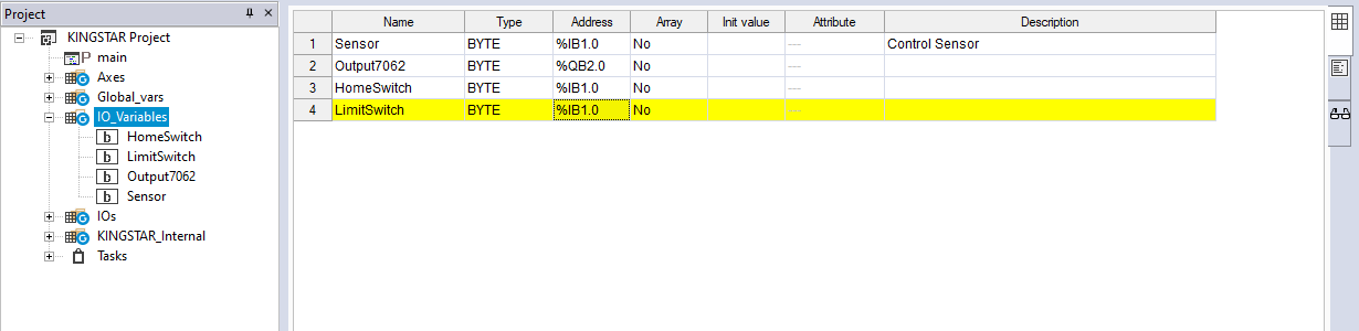
- In the Project panel, add LimitSwitch (any variable).
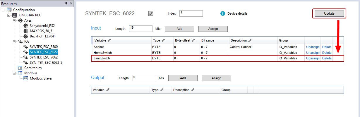
- In the Resources panel, click SYNTEK_ESC_6022. In the Resources panel in the middle, click Update in SYNTEK_ESC_6022 (your I/O module) to update the variables.
Change and display the bit address of the I/O variables:
You can change and display the bit address of the I/O variables.
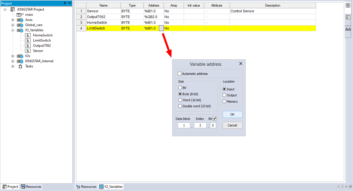
- In the Project panel, expand I/O_Variables. Double-click the variable you want to display its bit address. In this guide, we select LimitSwitch.
- In the IO_Variables panel, click the Address of LimitSwitch, and click the square in the Address cell to display the Variable address dialog box.
- In the Variable address dialog box, select the Bit check box to display the bit. You can edit the following three boxes to specify the variable address you want to use.
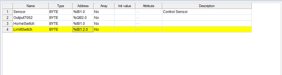
- The address is displaying the bit position.
Data block: the index of an I/O module. The index is zero based.
Index: the byte position. You can move the byte to the location you want. The index is zero based.
Bit: the bit position in a byte. You can move the bit to the location you want. The index is zero based. For example, if you want to use the first bit in the third byte in the second I/O module, the address will be 1.2.0.
When you're done, click OK.