|
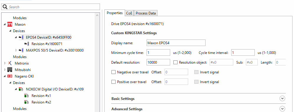
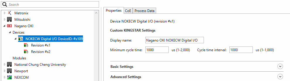
Displays the hardware profile. The user interface you see will vary depending on the device types you select is a drive, I/O or module. Under Custom KINGSTAR Settings: This area deals with the information not found in the ESI file but is necessary for the KINGSTAR Subsystem and must be provided for new devices. Display name: the product name used by KINGSTAR. Minimum cycle time: the minimum cycle time the device can accept. (The default value is 2000) This must be between 1 and 1,000 microseconds. For more information about the cycle time of your device, see its manual. Cycle time interval: the interval between the cycle times. Some devices only accept specific cycle times, such as 125, 250, 500. (The default value is 1000) Default Resolution: the default resolution of the encoder. This must be set according to the hardware manual. Resolution object checkbox: if this is checked, KINGSTAR will read the resolution information from the specified SDO object. Resolution Object: the index of the resolution object. It depends on if the drive has an SDO object containing the encoder resolution. Sub: the subindex of the resolution object. Length: the length of the resolution object. Negative /positive over travel checkboxes: Checked if negative /positive overtravel signal is supported. Negative Over Travel: the Negative Overtravel signal is supported. The DS402 standard specifies that the bit 0 of the drive digital inputs should be Negative Overtravel. Positive Over Travel: the Positive Overtravel signal is supported. The DS402 standard specifies that the bit 1 of the drive digital inputs should be Positive Overtravel. Offset: The bit offset of the drive digital input for the positive / negative over travel signal. The DS402 standard specifies that the bit 0 of the drive digital inputs should be negative overtravel, and bit 1 should be positive overtravel. Invert signal:Checked if the positive /negative over travel signal is inverted. |
Drive (EtherCAT device which is a drive):
I/O (EtherCAT device which is not a drive):
|
|
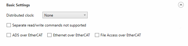
Expand Basic Settings to see the following: Distributed clock: the distributed clock. No clock: no clock. Sync 0: uses the Sync0 signal. Sync 1: uses the Sync1 signal. Sync 0 & 1: uses the Sync0 and Sync1 signals. Separate read/write commands not supported: It is selected if the device doesn't accept separate logical read/write commands (LRD, and LWR). It only accepts combined logical read/write command (LRW). ADS over EtherCAT (AoE), Ethernet over EtherCAT (EoE), File Access over EtherCAT (FoE): checked if it is supported by the selected device. |
|
|
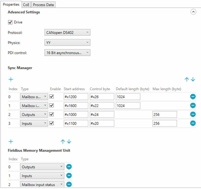
Expand Advance Settings to see the following: Drive: checked if the device is a drive. Protocol: the motion protocol used by this drive. Including None, CANopenDS402, MDP741, SercosOverEtherCAT, and BeckhoffKBus. Physics: Physic type of each port. 1st character: Physics of logical port 0 2nd character: Physics of logical port 1 3rd character: Physics of logical port 2 4th character: Physics of logical port 3 Allowed values: ‘Y’: MII ‘H’: MII - Fast Hot Connect ’K’: E-Bus(LVDS) ‘ ‘: Port not used(blank character) It should contain but not limit to these 4 values: YY, YKY, KK, and (empty). PDI control: process Data Interface Control, which defines how the EtherCAT chip connects to the EtherCAT slave's application.
Sync Manager Sync Manager ensures that the EtherCAT master and slave's access to the data in Dual-Port RAM (DPRAM) is synchronized. You can edit their settings in the corresponded fields. Index: The index of the sync manager. The default order is sorted by index. Mailbox output:: Transmit mailbox data from the master to slaves. Mailbox input:: Transmit mailbox data from slaves to the master. Outputs: : Transmit process data from the master to slaves. Inputs::Transmit process data from slaves to the master. Enable: checked = enabled: SyncManager active controlling memory; unchecked = disabled: No memory protection by SyncManager. The values of the Enable field for sync managers of type Inputs or Outputs are determined by KINGSTAR automatically. Start address: Physical start address of SyncManager Control byte: SyncManager Control Byte Default length (byte): Default size in bytes of SyncManager. (Visible for Mailbox input / output only.) Max length (byte): Maximum SyncManager length in bytes supported by the slave. (Visible for Inputs/Outputs only.)
Fieldbus Memory Management Unit (FMMU) Index: The index of the FMMU. The default order is sorted by the index. Type: ‘Outputs’: FMMU is used for output PDO ‘Inputs’: FMMU is used for input PDO ‘MBoxState’: FMMU is used to map the Write Event Flag of the Input Mailbox (register 0x080D.0) to the process data. The Input Mailbox does not have to be polled by the Master when waiting for a Mailbox Response. The usage is highly recommended to reduce traffic. |
|
See also