Reads data from the input, or reads and writes data to the output of the axis and I/O module.
Axis
The squares represent the inputs and outputs. Gray squares means the value of the input or output is FALSE. Blue squares means the value is TRUE. In the Output area, clicking one of the square can toggle the value between TRUE or FALSE.
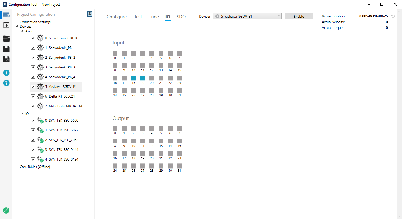
IO
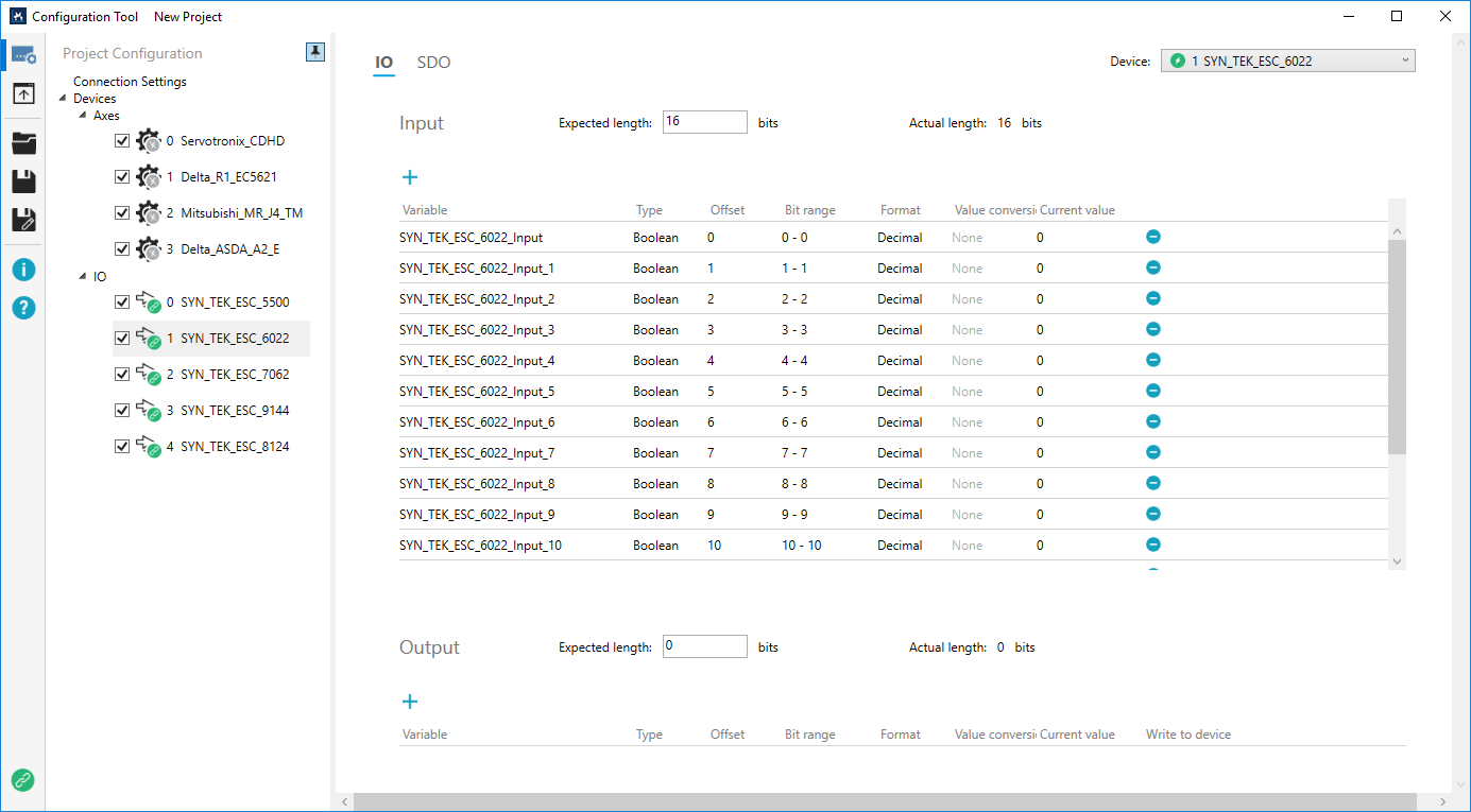
Loads the PDO variable list of the I/O module, which may have either inputs or outputs, or both of them, depending on the capabilities the module offers.
The definition of variables are retrieved from the ESI file. The Variable, Type, Offset, Format, and Write to device columns are editable. To edit, double-click the text in the field.
Input:
Output:
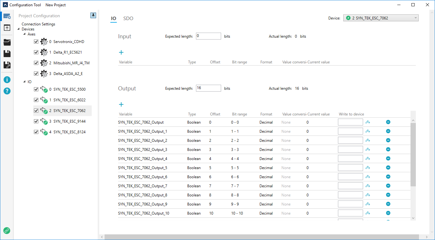
Expected length: the expected length of the input or output. If you don't need the whole length, you can enter a value less than that of the Actual length.
Actual length: the whole length of the input or output.
Blue plus (![]() ): adds a new variable to the input or output. If the input or output can't accept the variable, Bit range and Current value will be displayed in red.
): adds a new variable to the input or output. If the input or output can't accept the variable, Bit range and Current value will be displayed in red.
Variable: the variable of the input or output.
Type: the data type of the variable. Types: Boolean, Single, Double, Int8, Int16, Int24, Int32, Int64, UInt8, UInt16, UInt24, UInt32, UInt64.
Offset: specifies the offset to the location to be read or written. When the data type is Boolean, the offset unit is bit, otherwise the offset unit is byte.
Bit range: the range of the bit.
Format: the format of the value that is read from or to be written into the device. It's Decimal or Hexadecimal.
Value conversion: it is for those who use analog I/O modules and want to see a decimal value instead of a hex. The default setting is None. Click None to convert a value. After a value is converted, None will be changed to Enabled.
NOTE: Values can't be converted for I/O modules with Boolean.
No conversion: the entered value is not converted. Current value shows the value you write.
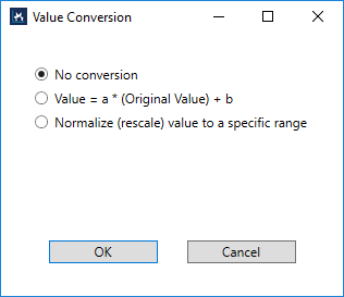
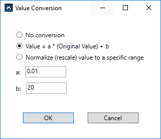
Value = a * (Original Value) + b: use the equation to convert your value. For example, you have the following settings for the equation:
Value = the entered value
A = 0.01
B = 20
When you enter 20 and click Write to device, you'll see Current value shows 20. Enter 21 to get 21, and so on. The program adds an Original Value and the conversion is done automatically. If you write a value in this conversion mode, and then switch to No conversion without changing the entered value, Current value will show the Original Value used in the equation.
For example, you enable this conversion mode and then write the value 21, Current value shows 21. Next, you switch to No conversion without changing 21, Current value shows 100, because 100 is the Original Value used to calculate the result 21.
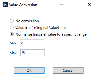
Normalize (rescale) value to a specific range: gives a range to control your machine. For example, you want to control the voltage range between 0V – 10V, so the Min and Max are like this:
Min: 0. Max: 10.
If you use an I/O module whose data type is UIn16, you can enter a value between 0 – 65535 to control 0V – 10V.
Current value: the current value.
Write to device: the value to be written into the variable. After you enter the value, press the Write icon (![]() ) to write.
) to write.
Delete ( ): deletes the variable. If you accidently delete the variable and you want get it back, do this:
- In Connection Settings, click Disconnect.
- Exit Configuration Tool.
- When it asks if you want to save the current project, click No.
- When it asks if you want to shut down KINGSTAR Subsystem, choose either Yes or No is okay.
- Start Configuration Tool.
- Open a project that is saved before you deleted the variable, or create a new project.
- Connect KINGSTAR to the same hardware.
- All the I/O variables are back and return to the default settings.
See also