In this page, you can convert the servo drive's unit to your own unit, reverse the axis' direction, limit the axis moving range (limit switch), set the axis' home switch, set the maximum and minimum acceleration, deceleration, and jerk of the axis. If your servo drive provides limit switch state in digital inputs, it will be used automatically if the digital inputs are enabled.
To enter this page, click on an axis device on the Project Configuration pane and then click the Configure tab on the Settings pane.
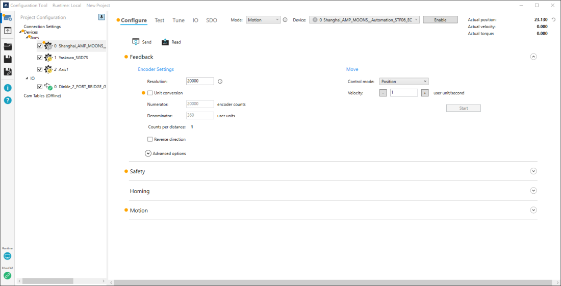
Send and Read

Send and Read offer the flexibility for you to decide whether to write and read the values from KINGSTAR Subsystem. If you are creating a new Configuration Tool project, after the hardware is connected, Configuration Tool automatically writes a set of settings into the KINGSTAR Subsystem for axes to use. These settings, configured by KINGSTAR, are applicable to most axes. With these settings, your axes can move properly (not extremely good though). When Configuration Tool is running, it keeps comparing the on-screen values and the ones stored in the Subsystem. If these values are changed either by you or other applications, the changed items will be marked. If you want to write the changed values into the Subsystem, you need to click Send, or the new values won't be written. If you have changed the values in some fields, but want to read the values from the Subsystem, click Read.
These two buttons are available only when the values are different from the ones in the Subsystem. After you click Send or Read, Configuration Tool will remind you the settings will be changed.
Send: applies the new values to the KINGSTAR Subsystem. After you click Send, Configuration Tool will remind you the settings will be changed.
Read: reads the values from the KINGSTAR Subsystem. After you click Read, Configuration Tool will remind you the values read will overwrite the values in the fields.
NOTE: If you open a Configuration Tool project, after the hardware is connected, Configuration Tool will use the settings you saved before.
NOTE: The Send and Read buttons in the Configure, Test, and Tune page are linked, which means if any setting that affects the axis has been changed in these pages, Configuration Tool will detect and mark it.
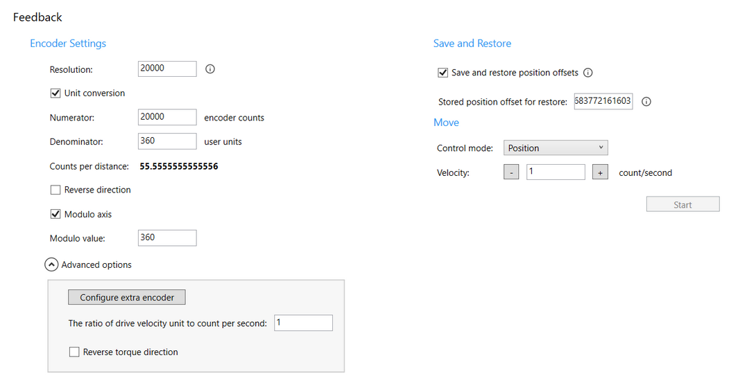
FeedbackProvides unit conversion and direction reversing. You can use the basic motion to test whether the feedback of the machine works well for new settings.
Encoder settingsIf the encoder settings are changed, Configuration Tool will remind you to change the values of homing, motion, and PID settings. Resolution: the resolution of a connected axis.
Unit conversion: enables the axis to use a real-world unit. Changing the unit affects the position and velocity. When this check box is cleared, Numerator and Denominator are not available. Numerator: converts the drive unit to the user unit. For example, if the device is an encoder, typically the numerator is the resolution of the encoder. Denominator: converts the drive unit to the user unit. For example, if you're using degree, the value will be 360 because there are 360 degrees in one revolution. Counts per distance: the number of encoder counts in one user unit. Reverse direction: reverses the direction the axis moves. Modulo axis: select this option to enable Modulo axis. Then, input a value in the Modulo value input box (e.g., 360). Advanced optionsConfigure extra encoder: if you have a second encoder, you can configure its settings here. The ratio of drive velocity unit to count per second: sets the conversion ratio of the servo drive's unit to the count (pulse) unit used by the axis. If the value is one, it means the axis is using count per second. Reverse torque direction: reverses the torque direction. Save and RestoreThis field appears only when the Save and restore position offsets option is selected in the Axis Settings section on the Connection Settings page. You can apply the Save and Restore Actual Position Offset feature to each axis. For more information on how to set up this feature, see Using the Save and Restore the Actual Position Offset Feature. Save and restore offsets: select this option to apply the Save and Restore Actual Position Offset feature to this axis. This option is unselected by default. Only the selected axes can have their offsets saved or restored when this feature is activated. When EtherCAT is disconnected, the stored value is displayed in the Stored position offset for restore field. You can change this value only if necessary. The value changed here is written only to the project file and is not written to the Position Offset file. MoveTests whether the axis works for the unit settings and the moving direction settings in Encoder Settings. Control mode: sets a control mode of an axis at run time. The control mode must be compatible with the current access mode. Not all axes support control mode changes at run time.
Start: starts the movement. |
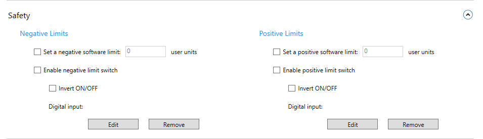
SafetySets the limit switch to control the distance the axis can move.
Negative limitsSet a negative software limit: sets the farthest position in the negative direction the axis can reach. Enable negative limit switch: enables the negative software limit.
Positive limitsSet a positive software limit: sets the farthest position in the positive direction the axis can reach. Enable positive limit switch: enables the positive software limit.
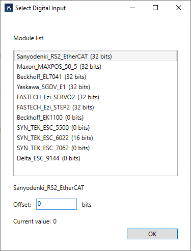
Select digital inputThe length of I/O module is Expected length. For details, see the IO page.
Module list: the list of the available I/O modules. Offset: specifies a bit offset to the location to read. Current value: the current value read from the module. |
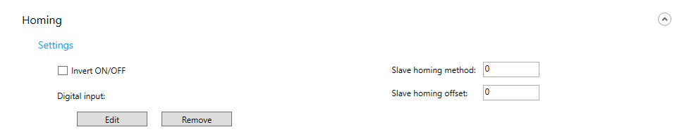
HomingSets a homing switch for an axis.
SettingsInvert ON/OFF: inverts the sensor value. When it is not selected, the sensor is considered touched as it is high (on). When selected, the sensor is considered touched as it is low (off). Edit: selects a digital input from the module list. Remove: removes the selected digital input. Slave homing method: uses the servo drive's homing features. For more information about the homing methods your servo drive provides, see its user guide. Slave homing offset: the distance the axis moves after it finds the homing sensor. |
Motion
Sets the motion parameters for an axis.
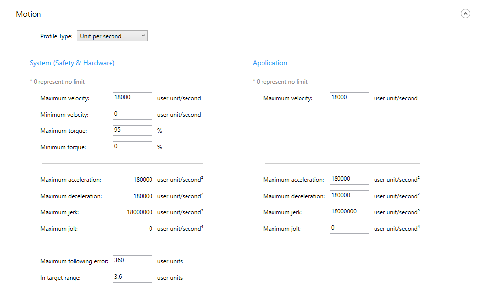
Profile type: sets the unit of acceleration and jerk for an axis.
Unit per second: acceleration in unit per second2 and jerk in unit per second3.
Delay in second: acceleration delay in seconds. It determines how much time the interpolation takes when it increases its velocity and accelerates from zero to the max velocity.
All the motion parameters in Configuration Tool are affected by Unit conversion (Feedback area) and Profile type (Configure > Motion). For more information about how Profile type works, see Concepts > Motion profile type.
| Unit per second | Delay in second | |
|---|---|---|
| Unit conversion (On) |
Target/Distance: user units Velocity: user units per second Acceleration: user units per second2 Deceleration: user units per second2 Jerk: user units per second3 Jolt: user units per second4 |
Target/Distance: user units Velocity: user units per second Acceleration: second Deceleration: second Jerk: second Jolt: second |
| Unit conversion (Off) |
Target/Distance: counts Velocity: counts per second Acceleration: counts per second2 Deceleration: counts per second2 Jerk: counts per second3 Jolt: counts per second4 |
Target/Distance: counts Velocity: counts per second Acceleration: second Deceleration: second Jerk: second Jolt: second |
System (safety & hardware)
Sets the motion parameters to the axis. If your servo drive or motor has some safety features or limitations, apply them here.
Maximum velocity: the maximum velocity of an axis. When it is set to zero, there is no limitation for the max value; when set to other values, the max velocity is the value you set.
Minimum velocity: the minimum velocity of an axis. When it is set to zero, there is no limitation for the min value; when set to other values, the min velocity is the value you set.
Maximum torque: the maximum torque of an axis. When it is set to zero, there is no limitation for the max value; when set to other values, the max torque is the value you set.
Minimum torque: the minimum torque of an axis. When it is set to zero, there is no limitation for the min value; when set to other values, the min torque is the value you set.
Maximum acceleration: the maximum acceleration of an axis.
Maximum deceleration: the maximum deceleration of an axis.
Maximum jerk: the maximum jerk of an axis.
Maximum jolt: the maximum jolt (change of jerk) of an axis.
Maximum following error: the maximum following error of an axis.
In target range: the position error of an axis. If the distance between the target position and actual position is less than this value, the axis is considered at the target position and the motion will be stopped.
Application
Sets the parameters to your KINGSTAR application.
Maximum velocity: the maximum velocity. When it is set to zero, there is no limitation for the max value; when set to other values, the max velocity is the value you set.
IMPORTANT: When you change Profile Type, the value in the following fields will be changed too, because each motion profile type has its own unit.
Maximum acceleration: the maximum acceleration. When it is set to zero, there is no limitation for the max value; when set to other values, the max acceleration is the value you set.
Maximum deceleration: the maximum deceleration. When it is set to zero, there is no limitation for the max value; when set to other values, the max deceleration is the value you set.
Maximum jerk: the maximum jerk. When it is set to zero, there is no limitation for the max value; when set to other values, the max jerk is the value you set.
Maximum jolt: the maximum jolt (change of jerk). When it is set to zero, there is no limitation for the max value; when set to other values, the max jolt is the value you set.
See also