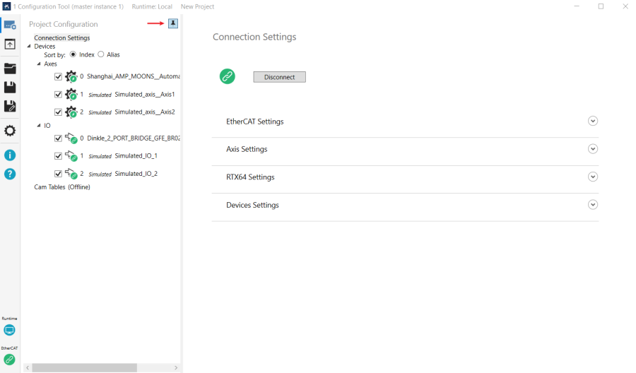
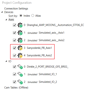
Displays the connected axes, I/O modules, and the cam tables in an auto-hide pane. The axis and I/O list appears only after you connect real devices or use simulated devices. You can configure their settings after connecting to devices.
|
Project Configuration is hidden on the left side. Click to display it, which covers part of the Connection Settings area. To hide the pane, click an area outside the pane. There is a pin button (where the red arrow indicates) on the upper-right corner of the Project Configuration. Click the icon to display the Settings area it covered, click it again to hide the pane.
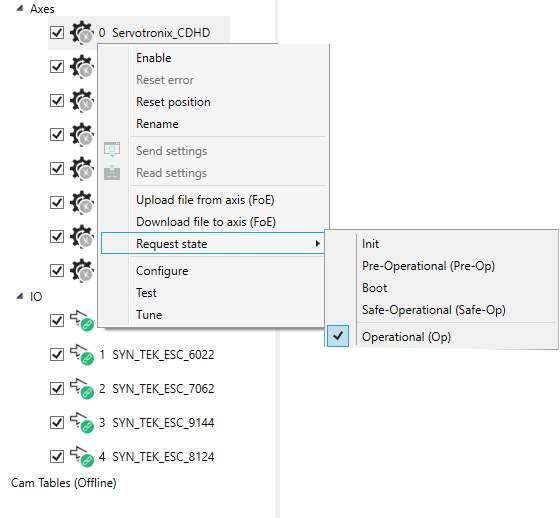
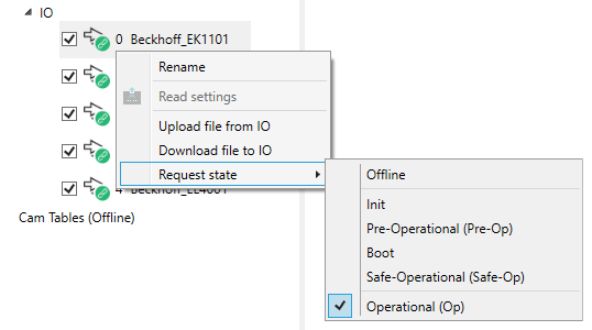
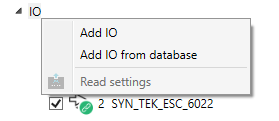
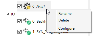
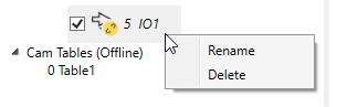
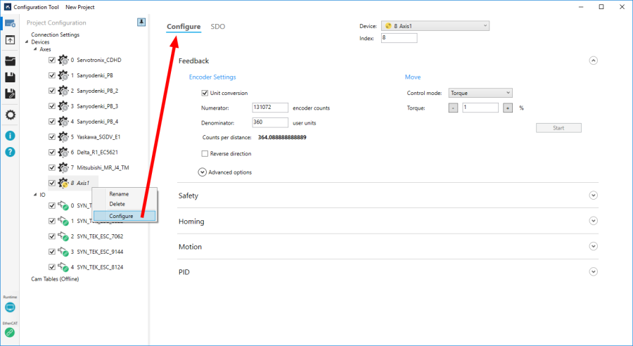
Context menuRight-click one of the axes to display the context menu.
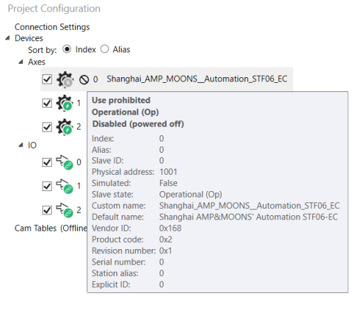
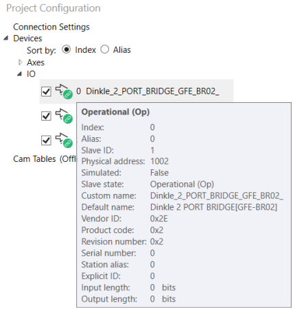
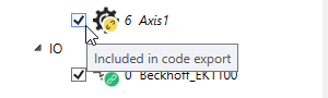
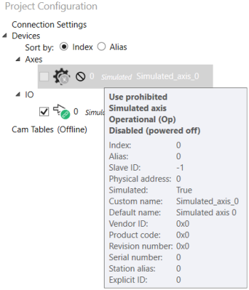
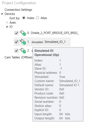
Tool tipsTool tip: to display the tool tip, move the mouse pointer over one of the axes or I/O modules. It shows the basic information of the device.
Add devices manuallyYou can add axes and I/O modules manually while Configuration Tool is online or offline.
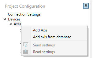
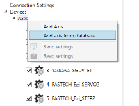
In the Project Configuration list, right-click Axes or IO to display the context menu. Add Axis: adds an axis. Add axis from database: adds an axis from the KINGSTAR hardware list. Add IO: adds an I/O module. Add IO from database: adds an I/O module from the KINGSTAR hardware list. Add an offline axis or I/O moduleThe ways to add an offline axis and I/O module are the same. In this guide, we add an offline axis.
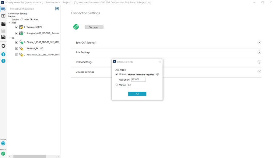
Axis mode
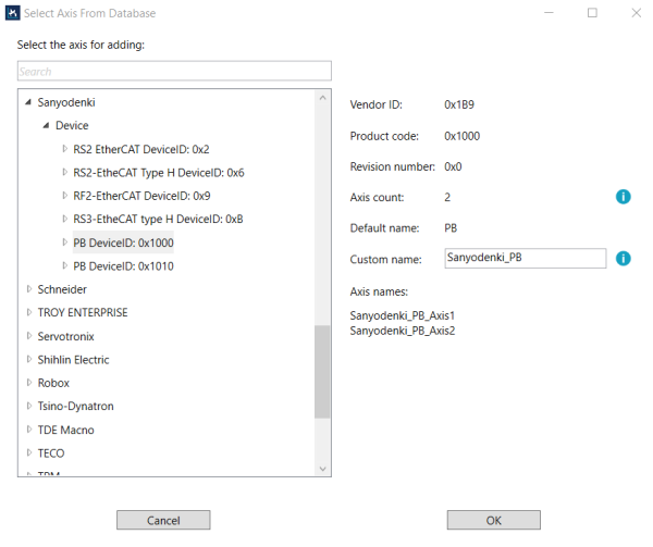
Switching Axis mode will also switch the internal control mode. The configurations will be saved automatically. Add an axis or I/O module from databaseThe ways to add an axis or I/O module from the KINGSTAR hardware list are the same. In this guide, we add an axis from the list.
NOTE: For multi-channel drives, the Axis count field shows the number of axes, and the Axis names field automatically lists them in the format Drive name + Axis number.
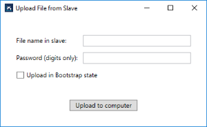
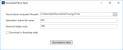
NOTE: For multi-channel drives, clicking OK will add all of its axes. Edit the offline axis or I/O moduleTo edit an offline axis or I/O module, right-click it and select a command on the context menu.
Change the index of the offline axis or I/O moduleIn the Configure page of an offline axis or I/O module, you can change the index of the device. Remember if both online and offline devices exist in the list, the offline ones can use only the indexes not occupied by the online ones.
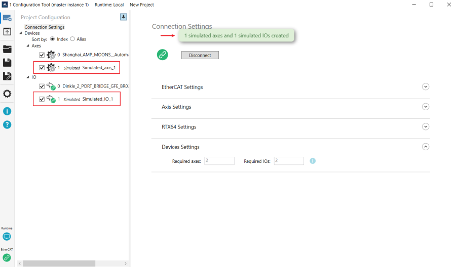
Simulated devices reminderWhen you create simulated axes or I/O modules in Connection Settings, or if the real hardware is not connected properly, a message is displayed to remind you the simulated devices are created. Simulated hardware names are prefixed with the word Simulated. NOTE: In the tooltip, the default value of Simulated is shown as "False" when adding devices manually. Once connected to the simulated device, it is shown as "True".
Cam tablesThis area displays the cam tables you added. For more information about how to use it, see Work with Configuration Tool > Cam Tables. |
See also