Tweaks the PID parameters using KINGSTAR to optimize the control system. The graph displays the result from the servo drive's PID control. Depending on the control mode you select, the result shows velocity, position, or torque curves. For example, if you select the Torque mode, the graphic shows the interpolation torque and actual torque. The closer they match, the better the result.
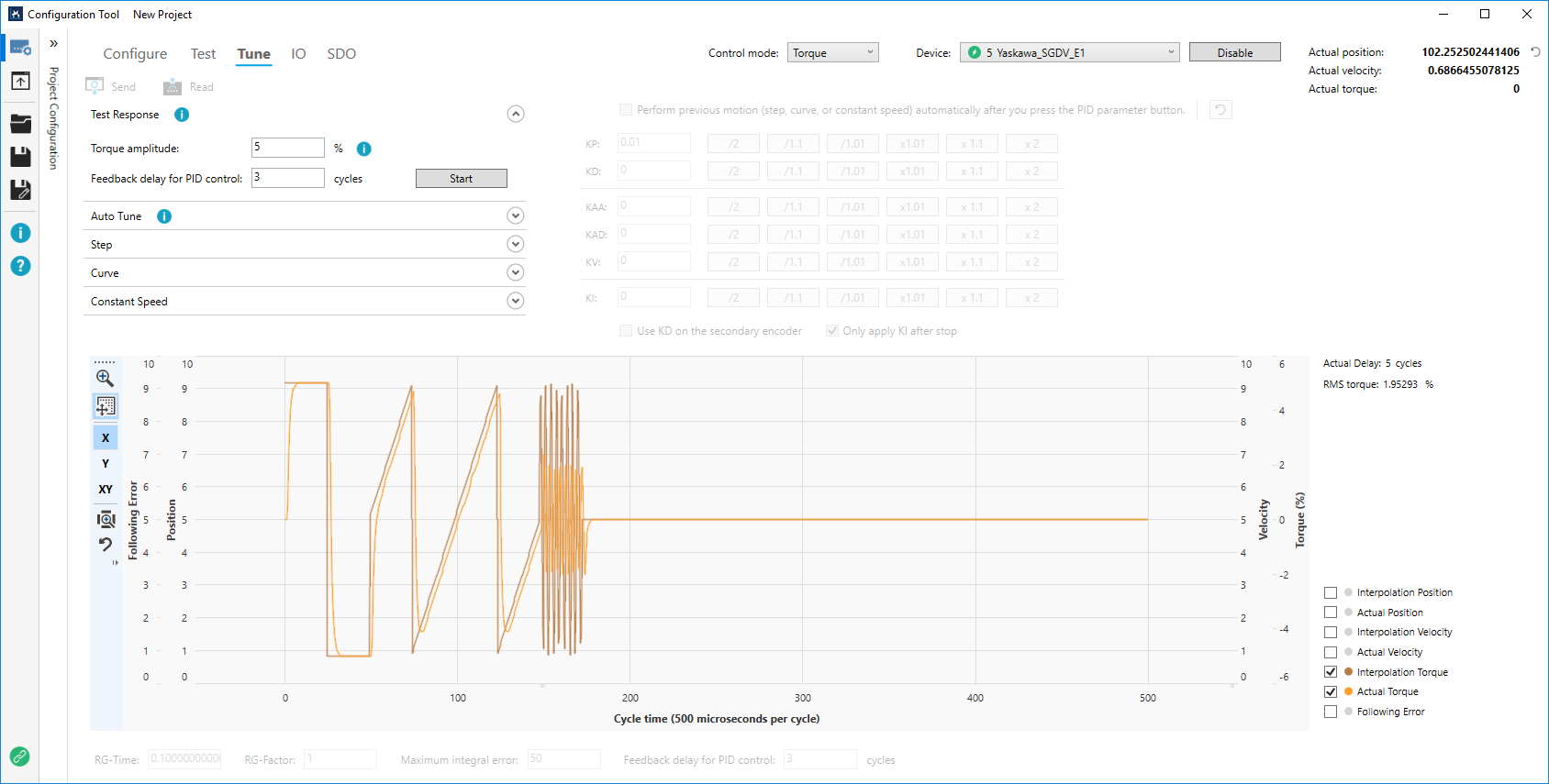
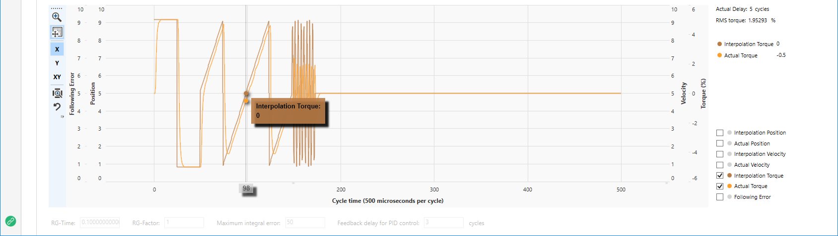
Each property is represented by a color. Select or clear the properties check boxes to see their curves. To see the value the curve traces, place the mouse pointer on the graph and hover the pointer over the color points on the curve.
All the motion parameters in Configuration Tool are affected by Unit conversion (Configure > Feedback) and Profile type (Configure > Motion). For more information about how Profile type works, see Concepts > Motion profile type.
| Unit per second | Delay in second | |
|---|---|---|
| Unit conversion (On) |
Target/Distance: user units Velocity: user units per second Acceleration: user units per second2 Deceleration: user units per second2 Jerk: user units per second3 Jolt: user units per second4 |
Target/Distance: user units Velocity: user units per second Acceleration: second Deceleration: second Jerk: second Jolt: second |
| Unit conversion (Off) |
Target/Distance: counts Velocity: counts per second Acceleration: counts per second2 Deceleration: counts per second2 Jerk: counts per second3 Jolt: counts per second4 |
Target/Distance: counts Velocity: counts per second Acceleration: second Deceleration: second Jerk: second Jolt: second |
Topics:
Send and Read
The Send and Read buttons in the Configure, Test, and Tune page are linked, which means if any setting that affects the axis has been changed in these pages, Configuration Tool will detect and mark it. For more information about the buttons, see Configure > Send and Read.
In the Tune page, the settings related to Send and Read are PID parameters (including the ones under the graph).
Send: applies the new values to the KINGSTAR Subsystem. After you click Send, Configuration Tool will remind you the settings will be changed.
Read: reads the values from the KINGSTAR Subsystem. After you click Read, Configuration Tool will remind you the values read will overwrite the values in the fields.
Test response
Tests the servo drive's PID control and sees whether the axis is working properly. Depending on your control mode, KINGSTAR sends the position, velocity, or torque commands directly to your servo drive, and draw a graph based on the drive's feedback. If the feedback is good, it means the drive responds well to the selected control mode, otherwise you may need to tune the servo drive using its tool, or using other control mode. To know whether the feedback is good, see Tune in Work with Configuration Tool.
Move (Position mode) / Amplitude (Velocity mode) / Torque amplitude (Torque mode): how far the axis moves. The unit varies between control modes. See Device configuration to learn the unit.
Velocity: the velocity of an axis. This is available only in Position mode.
Feedback delay for PID control: the number of cycles that KINGSTAR backtracks to compare the actual position with the commanded position sent before. Usually it's 3 cycles.
Start: tests the axis using the current settings.
Auto Tune
Generates a set of usable PID parameters for users by running Step and T-curve tests repeatedly. Auto Tune is available in Velocity and Torque modes. You can use Auto Tune to get a set of usable PID quickly, and then manually fine-tune the PID based on the values Auto Tune gives so that the PID best meets your needs. You can keep the PID by saving it to a .kst file or make a note of it.
Auto Tune may fail due to the instability of machine, but even if it fails, you still get a set of PID values for reference. You can keep manually tuning the PID based on the values Auto Tune gives you, until it works properly and meets your needs. This way, you can find the usable PID more quickly than manually tuning it from the beginning.
We suggest you use the following cycle time for Auto Tune:
Velocity mode: 1 millisecond or less
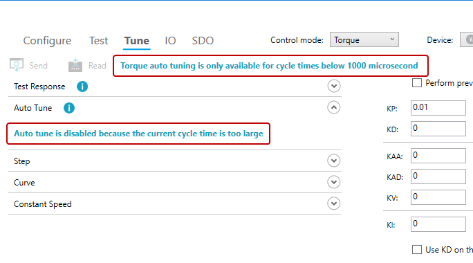
Torque mode: 500 microseconds or less.
IMPORTANT: Poor performance, errors, or damage may be incurred if you use the cycle time we don't recommend.
NOTE: Auto Tune is disabled if your cycle time is too slow. To use Auto Tune, go to Connection Settings -> EtherCAT Settings and decrease Cycle time's value.
NOTE: While Auto Tune is running, the Use KD on the secondary encoder check box is automatically cleared, because the parameters Auto Tune gives you are only for primary encoder. If you have to use the secondary encoder, you need to manually tune the PID.
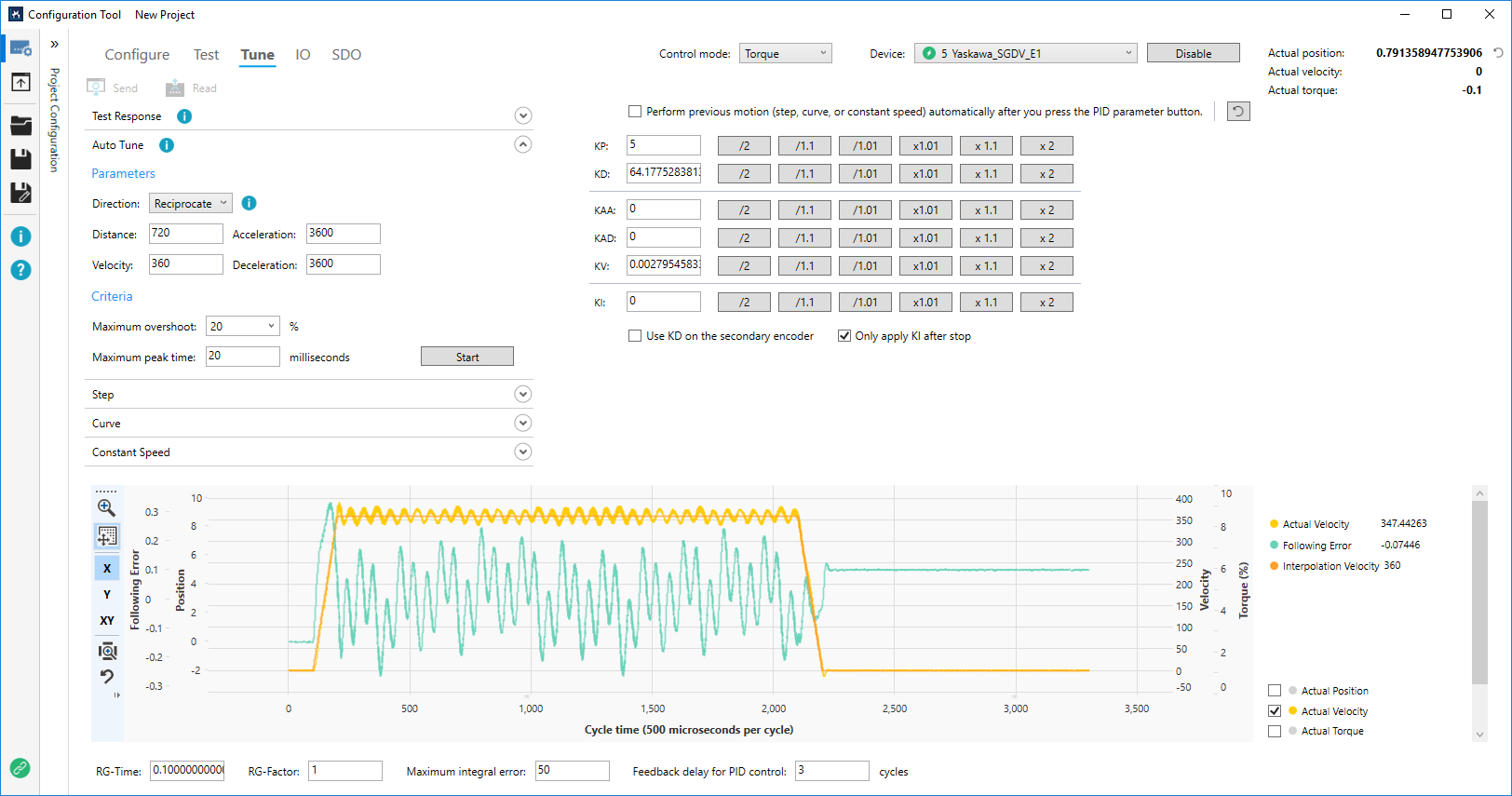
Direction: the direction of T-curve moves. By default, it is Reciprocate.
One way: the axis moves in one direction. The direction is determined by the value of Distance. If Distance is positive, the direction is positive, otherwise it is negative. By default it is positive.
Reciprocate: the axis moves back and forth.
Distance: the distance of a T-curve move. The value can be positive or negative, which affects Direction.
Velocity: the velocity of a T-curve move. The value should be equal to or greater than zero.
Acceleration: the acceleration of a T-curve move. The value should be equal to or greater than zero.
Deceleration: the deceleration of a T-curve move. The value should be equal to or greater than zero.
Maximum overshoot: the percentage that determines how much an axis overshoots Step distance. It is available only in Torque mode.
Example:
Starting position: zero
Step distance: 10
Overshoot: 12
Maximum overshoot:  =
=  =
=  = 20%
= 20%
Maximum rise/peak time: the amount of time a signal changes from a specified low value to specified high value. The lower the value, the shorter the time and the faster an axis moves. The higher the value, the longer the time and the slower an axis moves.
Maximum rise time (Velocity mode): the amount of time an axis' position moves from the starting position to 63.2% of the distance in Step tests. For example, if you want your axis to move from zero to 10, the rise time is 6.32.
Maximum peak time (Torque mode): the amount of time an axis moves from the starting position to the position where the maximum overshoot occurs in Step tests.
Step distance:
It is an internal parameter set to 1/36 revolution. If you convert the unit to degrees, this parameter will be 10 units. If no unit conversion is used, it is 1/36 x revolution counts.
Example:
Counts per revolution: 10000
Step distance: 10000 x 1/36 ≈ 277.78

Rise Time

Peak Time

Step
Commands a very small move and checks if the response to that move is quick enough. The difference between the actual position and interpolation position after applying corrections is a steady-state error.
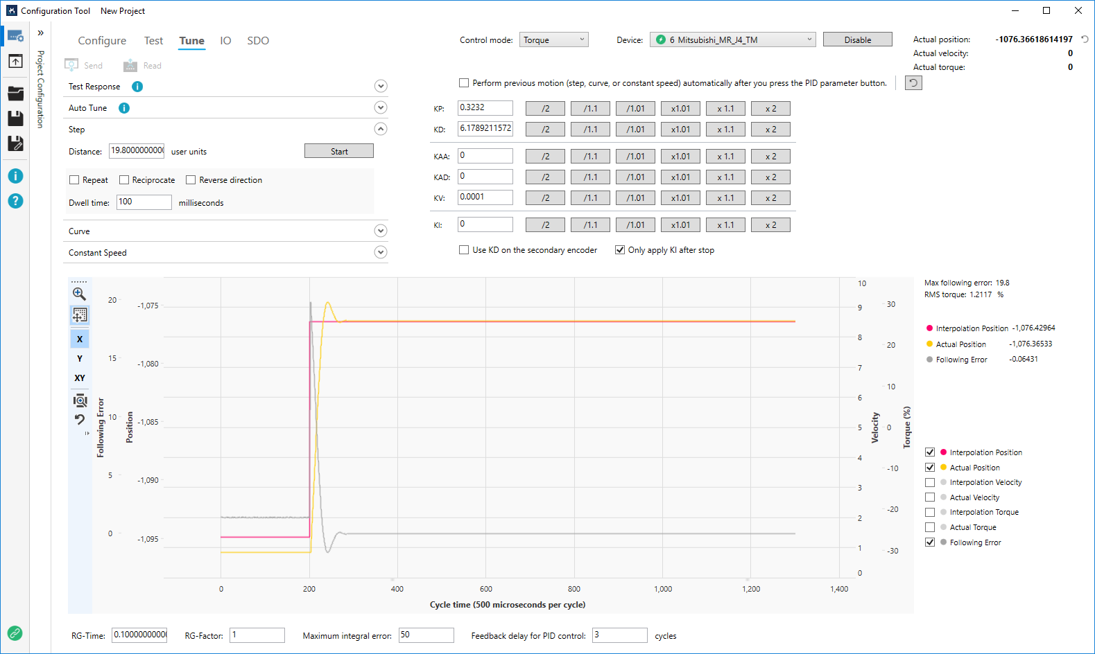
Distance: sets distance for a step move for tuning.
Start/Stop: starts or stops the step movement. After you press Start, it becomes Stop.
Repeat: repeats the last action. If you press Start after selecting this check box, the system will keep calculating and generating the new graph of motion profile, until you press Stop.
Reciprocate: moves back and forth.
Reverse direction: reverses the moving direction.
Dwell time: adds extra seconds to see what the axis does after it completes the move before drawing the graph. This is to confirm that all motion is included in the graph. For example, if the move takes one second and Dwell is 0.2, it takes 1.2 seconds to draw the graph.
T & S curve
Creates a velocity profile from a trapezoidal or S curve. When you use Curve, focus on the interpolation velocity and following error.
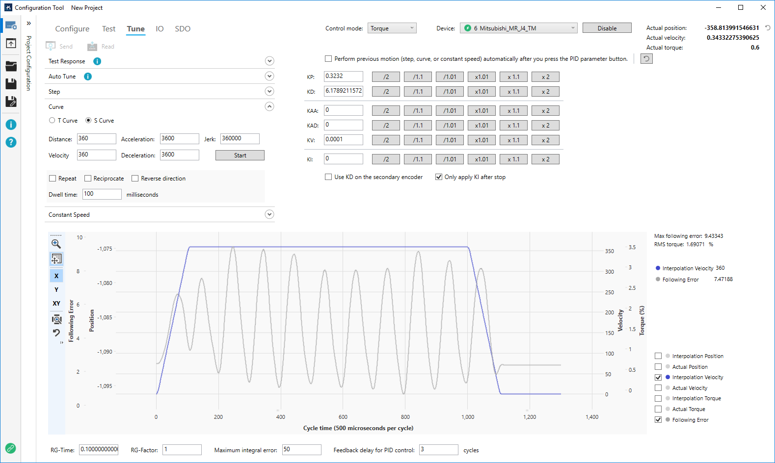
T Curve: creates a trapezoidal curve from a velocity profile.
S Curve: creates an S curve from a velocity profile.
Distance: how far the axis moves.
Velocity: velocity.
Acceleration: acceleration.
Deceleration: deceleration.
Jerk: jerk.
Start: starts the movement.
Other options: see the description in Step.
Constant speed
Uses the constant speed to run the axis for a period of time to test its performance.
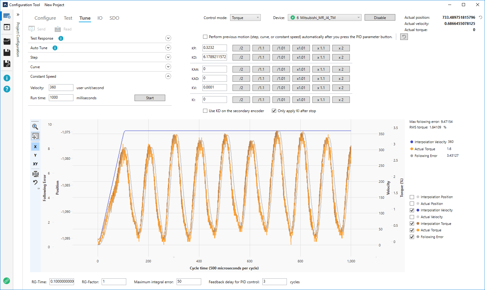
Velocity: the velocity of the axis.
Run time: how long the test of constant speed runs.
Start: starts the test of constant speed.
PID parameters
Uses proportional, integral, and derivative algorithm to deal with the errors generated during the process, and calculates a proper output value for the control system.
Perform previous motion automatically after you press the PID parameter button: repeats the last action when the value of a PID parameter is changed. For example, the last action is creating an S curve from the velocity profile. If you select this check box and press KP's x2, the system will multiply the KP value by two and create an S curve with that value.
Reset to default (  ): resets all PID parameters to their default values.
KP: proportional gain.
KD: derivative gain.
KAA: acceleration feedforward gain.
KAD: deceleration feedforward gain.
KV: velocity feedforward gain.
KI: integral gain.
/2: divides the value by 2.
/1.1: divides the value by 1.1.
/1.01: divides the value by 1.01.
x1.01: multiplies the value by 1.01.
x1.1: multiplies the value by 1.1.
x2: multiplies the value by 2.
Use KD on the secondary encoder: uses KD on the secondary encoder.
Only apply KI after stop: uses KI on the steady-state error.
RG-Time: determines when the axis starts using RG-Factor after finishing the move. Unit: second. RG: Reduced Gain.
RG-Factor: KP, KI, and KD multiplied by this factor after RG-Time.
Maximum integral error: the maximum integral error. When you use KI, you need to specify a number for this value.
Feedback delay for PID control: the number of cycles that KINGSTAR backtracks to compare the actual position with the commanded position sent before. Usually it's 3 cycles.
See also