This section provides the information about the user interface of KINGSTAR Configuration Tool.
When launching the KINGSTAR Configuration Tool through the KINGSTAR Control Panel, a "Connect to KINGSTAR Runtime" dialog box appears.
- Connect to local Runtime: This option is only available on the computer with KINGSTAR Runtime installed. Select to connect the Configuration Tool to the local KINGSTAR Runtime. You can select an instance ID by inputting an ID in the Instance input box.
- Connect to remote Runtime: Select to connect the Configuration Tool to the remote KINGSTAR Runtime. Fill in the username of that remote computer, select the user role and fill in the password. You can select an instance ID by inputting an ID in the Instance input box.
Note that an OPC UA server connection information is needed for remote connection. Please see OPC UA Server for details about how to configure the server; and see KINGSTAR OPC UA for understanding more about KINGSTAR OPC UA.
NOTE: The Instance input box only appears if you have created instances on the General Settings page of KINGSTAR Control Panel. You can input an instance ID to launch the Configuration Tool. The selected instance ID will be displayed on the title bar of the Configuration Tool.
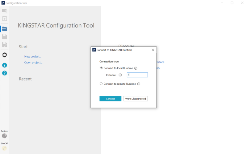
Click Connect, the Configuration Tool has been connected to the selected KINGSTAR Runtime.
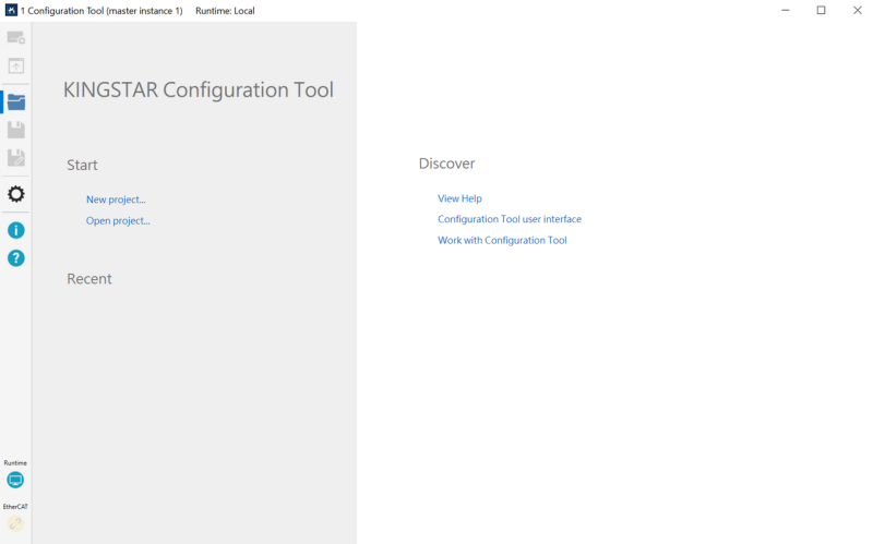
Click New project to start a new project by connecting the hardware devices for configuration (please refer to Configure the settings for more details). Once connected, you can start using the Configuration Tool. Below are the descriptions of the user interface:
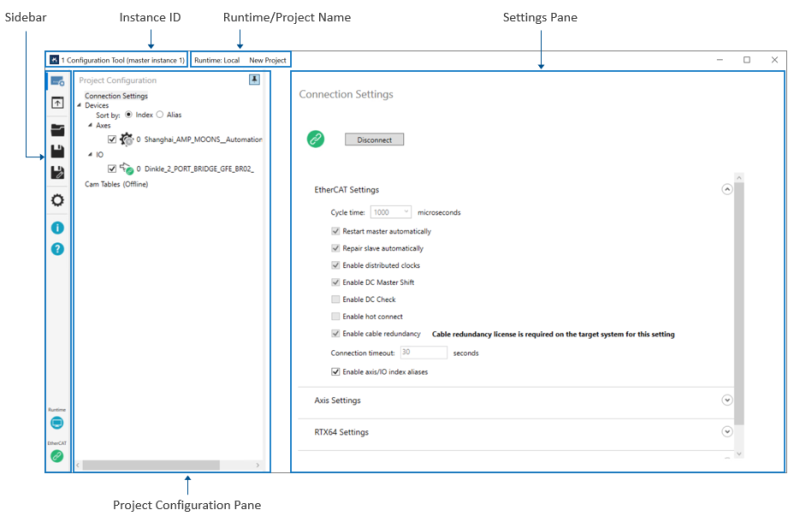
[Sidebar]: deals with devices and files. The icons from top to bottom are listed as below.
- Project Configuration: click to display the Project Configuration pane. The pane displays the connected axes, I/O modules, and the cam tables. The axis and I/O list appears only after you connect real devices or use simulated devices. You can configure their settings after connecting to devices. Click the icon on the upper-right corner of the pane can pin/unpin/expand/collapse the pane.
Click on a device, a Settings pane to the selected device displays on the right-side. You can configure the settings on the Settings pane.
- Device configuration: allows you to select a device and its control mode, and shows its position, velocity, and torque.
- Configure: sets the parameters that affect how axis moves, such as encoder's unit, axis moving direction, limit switch, homing and motion.
- Test: provides basic motion to test the movement for axes.
- Tune: tests a servo drive's PID control and see how the servo drive works in different control mode. You can tweaks the PID parameters to optimize the control system.
- IO: reads data from the input, or reads and writes data to the output of the axis and I/O module.
- SDO: provides data access to the device through Service Data Object (SDO).
- Export Settings: exports all settings you configured in the Configuration Tool to C++ code.
- Open (Startup Page): click to display the start page of the Configuration Tool, in which you can create or open a project file, or read the Configuration Tool help.
- Save: click to save the current settings to a folder.
- Save As: click to save the current settings to a new folder.
- Options: click this icon and check the Support index alias option to turn on the alias feature in Configuration Tool. You can then configure aliases for axes or I/Os and display devices in alias order. See Display Devices in Alias Order for more details.
NOTE: If you connect from a remote Runtime, you can change the language for your Configuration Tool in the Options setting. See Step 2 in Language for more details.
- About: the version and copyright information of Configuration Tool.
- Help: click to display the Configuration Tool help.
- Runtime: the Runtime button is used to connect/disconnect to/from the Runtime computer.
- EtherCAT: this button shows the EtherCAT connection status. You can click the button to connect or disconnect the Subsystem from the hardware. It works the same way as the Connect button on the Connection Settings page. You can also use this button to check the connection state.
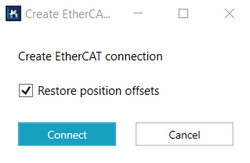
- When connecting to EtherCAT, you can select the Restore position offsets option and click Connect to connect and restore the position offsets from the Position Offset file. This works the same way as the Connect and restore position offsets button at the top the of Connection Settings page.
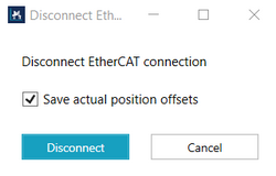
- When disconnecting from EtherCAT, you can select the Save actual position offsets option and click Disconnect to save the position offsets of the selected axes to both the Position Offset file and the project file, and then disconnect the EtherCAT connection. This works the same way as the Save position offsets and disconnect button at the top the of Connection Settings page.
If you have enabled the Save and Restore Actual Position Offset feature and selected the Save and restore position offsets option for the selected axes, clicking the EtherCAT button will prompt the following dialog when connecting to or disconnecting from the EtherCAT connection.
[Instance ID]: displays the selected instance ID. Note that if instance 0 is selected, the title bar will not show the ID.
[Runtime/Project Name]: displays the selected Runtime and project name. If you create a new project file, it displays the file name; if you load a project file, it displays the saved file name and its file path.
[Settings Pane]: displays the content of the command you select from Sidebar.
[Project Configuration Pane]: after clicking the Project Configuration icon on the Sidebar, the Project Configuration pane displays here. You can click the icon on the upper-right corner of the pane to pin/unpin/expand/collapse the pane.